
Wasserwipf
Smash Apprentice
Hallo everyone. I think I got something interesting for all of you, but first things first: -Please read!-
-I didn't know where to post this, but since Smash 4 Wii U will feature Gamecube Controller (in the future just GCC) I thought I'd post it here.
-I'm not a native English speaker, please bear with me (grammar etc.)
-Warning: Maybe large pictures. I decided to keep them large so that you can see detail if you want to")
-Warning: Wall of text.
-I dunno if somebody made this before, but whatever, I havent seen it so probably a few others don't know this as well.
Ok, here we go:
So, about 10 years after I bought my Gamecube, hundreds of hours played, and two years of competitive Smash, I managed to wear my GCC out. It's control stick wasn't working well enough anymore, the rubber had gone off, and a few other stupid flaws, I decided to open up my GCC and look what's inside. Since I had a 3rd party GCC, where the connection cable broke, my ulterior motive was to kind of build a "hybrid" controller, or at least see what's possible.
Let's start with the comparison and stuff, i try to order it a bit. Pictures in Spoilers.
Opening:
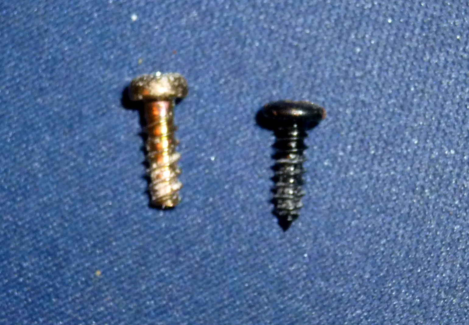
So I grabbed my screw driver and... oh god those screws. The screws of the 1st party GCC (in the future 1pGCC) were apparently custom made. They had a triangle socket head (usually you have eg slotted heads) and was almost impossible to open. I managed to do it, but i destroyed the head of the screws in the process.
There are six of them in total, 2 of them counter-sunk, and incredibly hard to remove.
The 3rd party GCC (3pGCC) however had standard type screws and was relieving easy to open.
The GCC consist of 2 major parts. The shell and the electronics. The shell is a two piece plastic and what you hold in your hands.
The 1pGCC was really well made, you could separate the electronics from the shell without any problem, because you could plug all the parts.
The 3pGCC's electronics was connected with the top part of the shell, and I had to remove a few screws to complete remove them. And the rumble part was flying around, but I'll catch that later on.
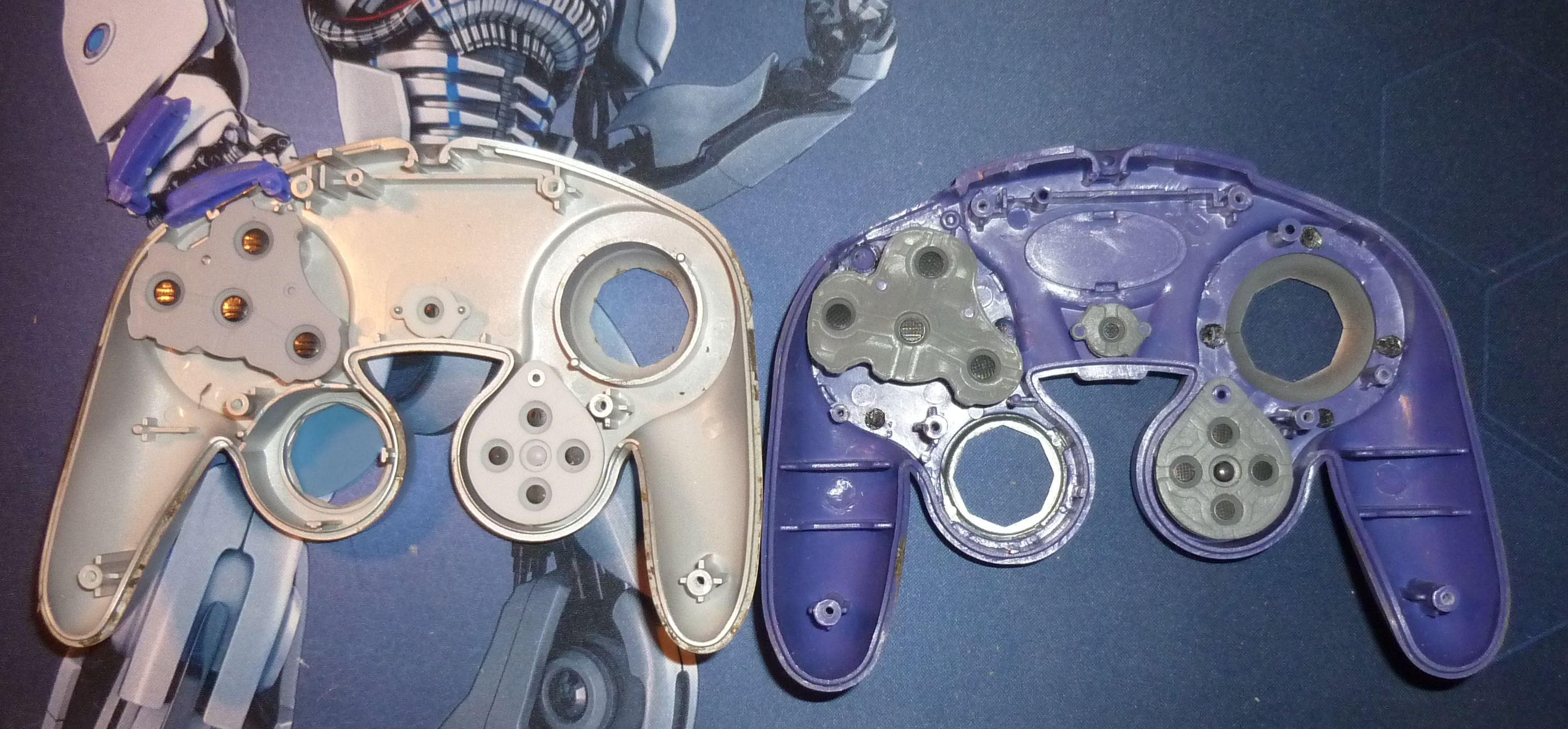
Here you have the two Top shells together....
Basically the two are one and the same except a few details. The 3rGCC (the purple one, btw) is a bit wider.
Electronics:
IMO the second most interesting thing. I'll split that up a little wider, since the rest is almost only electronics
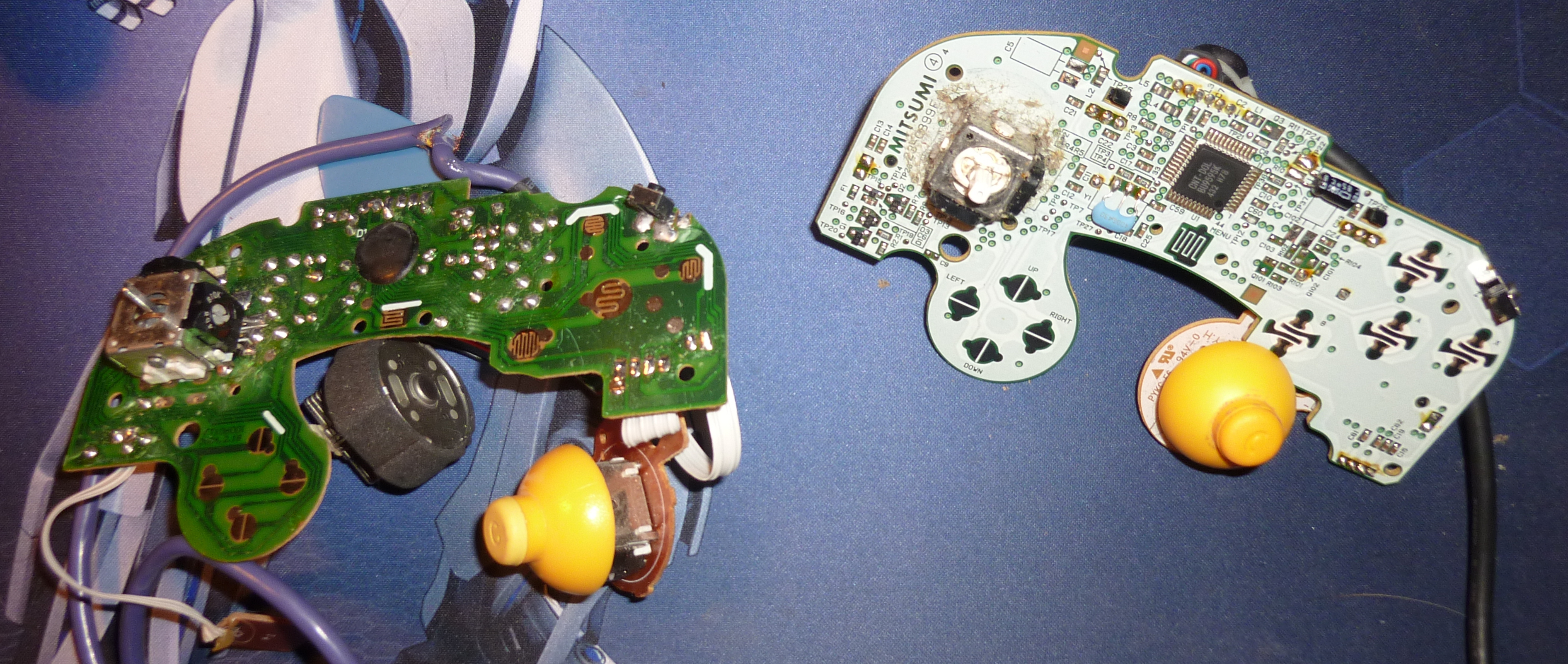
So first off, here you have the "Motherboard" of the 1pGCC.
No seriously, I laughed so hard when I saw that.
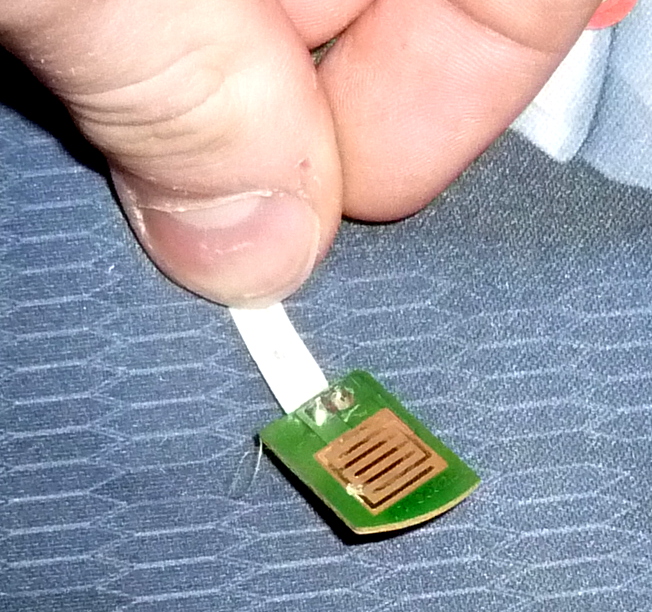
However, back to the picture before, a bit of explanation: Those little metal parts you can see are what reads and processes your inputs.
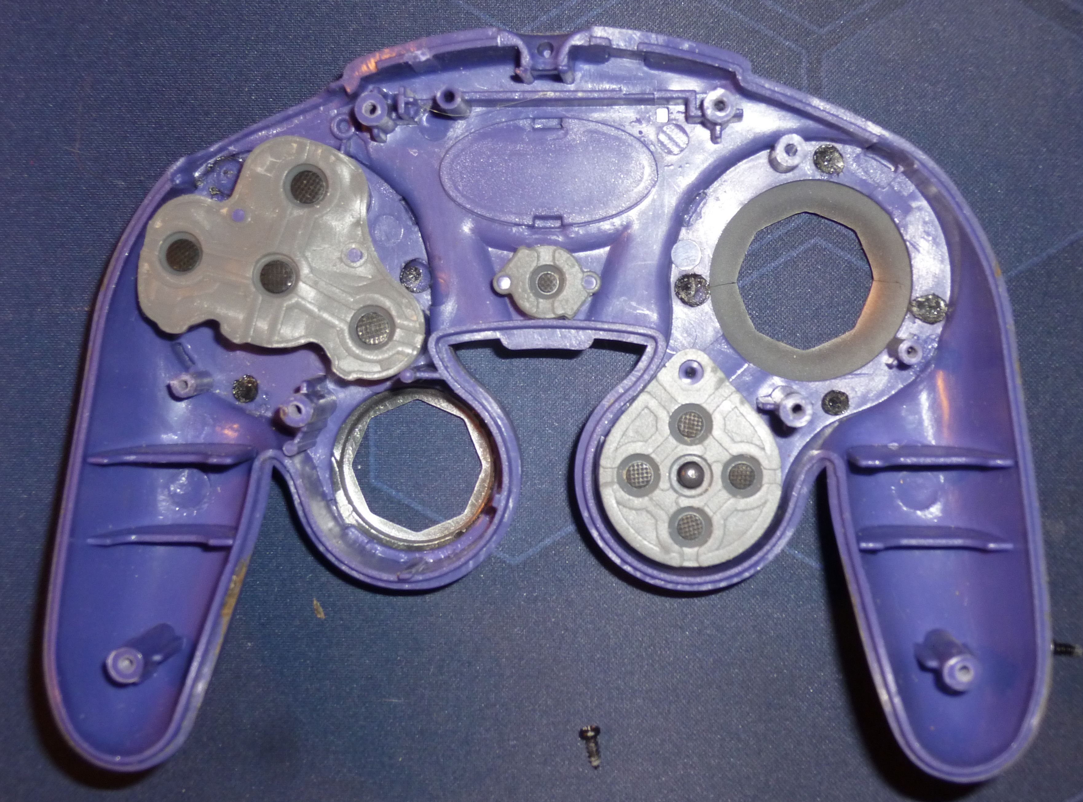
If you look back to the picture of the Top Shell you'll notice some round metal plates on the back of where the buttons are. Now when one of those buttons is pressed, it connects the four metal parts of the main board of the appending button, connect them and allow the electricity to flow. That's how computers basically work.
However, i honestly don't know why there are 4 and not two, but whatever.
The next rather interesting thing is on the back of the main board,
the Rumble.
The winner here is, once again, the 1pGCC. Why? The rumble is connected directly to the main board, and thus easy to handle.
Take a look:
The electric motor brings the half-round metal part to rotation, and the controller starts shaking. And that half round metal part consists of many small plates, simply because the manufacturing is cheaper
Control stick:
I was really surprised on how it worked. The control stick has like 2 spheres interleaved where one does the X and the other the Y axis... ok, it's hard to explain, maybe those pictures will help:
So that thing is quite cool, but it apparently stats loosening up a bit after usage (that's what happened to me as well. It was so loose it would go to random directions if idle)
And here 3p, quite similar, works as well.
It seems like there's a spring inside, and the spring of the 3pGCC fells way stronger. However, I didn't use it too often, so that might be the reason...
Now, for all you Powershielder, Wavedasher and l-canceller out there, the most interesting part,
the triggers (are they even called trigger? Whatever)
L and R are both mounted in the bottom half of the shell. 1p and 3p use similar systems, but 3p needs an additional part that's mounted with screws to hold the trigger in place.
The triggers consist of 3 parts, but take a look yourself:
The triggers press on the following part,
Next up only the triggers:
So you can switch triggers rather easily.
And even more interesting:
So it take more force to press L on the 3p.
So what did I do? since i couldn't really repair the Control stick, i went on and:
I replaced the L of the 1p with the one of the 3p, including its spring.
After a few tests I found pros and cons:
Complete con: 3p is a little bit longer, causing the trigger to stuck sometimes. Needs a bit of reworking, but works fine afterwards
Pro: Its ridiculously awesome to have R and L with completely different pressure forces. That's like, amazing. The 3p L gives u so much feedback, the moment you let it go it springs back in idle position. Where as the right one is really fast pressed. 3p is really good for Wavedashing, while as 1p works great for power shielding IMO.
However, my controller broke completely soon after, so I'm back to using normal GCC (I'm so glad i still found some. No really, getting those here in Switzerland is really hard. That was basically why I even started the hole thing)
Ok, with this I'm almost finished. If you have any questions feel free to ask.
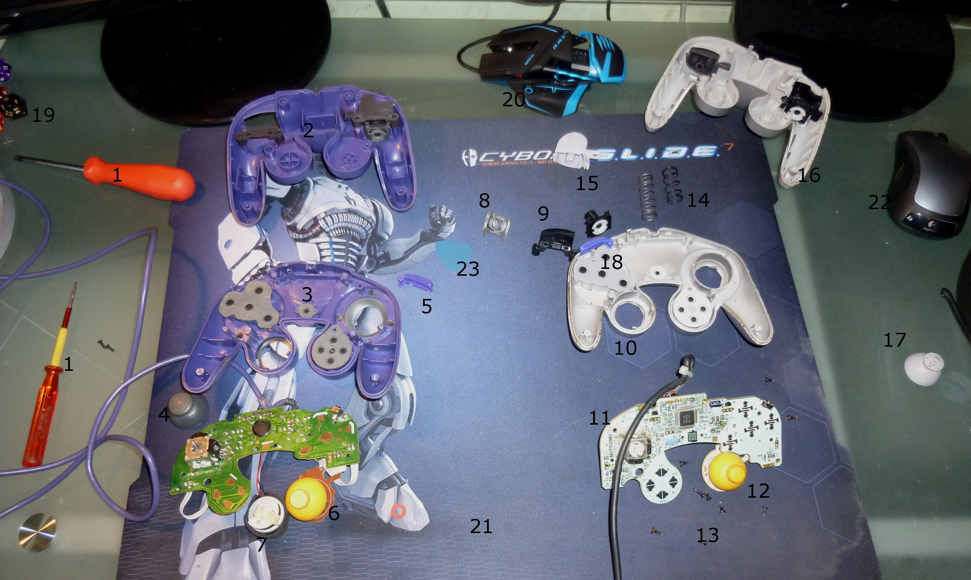
Here a complete picture of my working ground and everything, and after it additional pictures. Thanks for reading
1: Screwdrivers; 2: Bottom 3p; 3: Top 3p; 4: Control stick 3p; 5: Z 3p; 6: C-Stick 3p; 7: Rumble 3p; 8: R input 3p; 9: L cover 3p; 10: Top 1p; 11: Main board; 12: C-Stick; 13: Screws; 14: Springs; 15: L 1p; 16: Bottom 1p; 17: Control stick 1p; 18: Backside of the Buttons 1p, Z; Misc: 19: 20 sided Die... definitely not for D&D; 20: My mouse; 21: mouse board... for my mouse; 22: my err... other mouse.
Have Fun!
-I didn't know where to post this, but since Smash 4 Wii U will feature Gamecube Controller (in the future just GCC) I thought I'd post it here.
-I'm not a native English speaker, please bear with me (grammar etc.)
-Warning: Maybe large pictures. I decided to keep them large so that you can see detail if you want to
-Warning: Wall of text.
-I dunno if somebody made this before, but whatever, I havent seen it so probably a few others don't know this as well.
Ok, here we go:
So, about 10 years after I bought my Gamecube, hundreds of hours played, and two years of competitive Smash, I managed to wear my GCC out. It's control stick wasn't working well enough anymore, the rubber had gone off, and a few other stupid flaws, I decided to open up my GCC and look what's inside. Since I had a 3rd party GCC, where the connection cable broke, my ulterior motive was to kind of build a "hybrid" controller, or at least see what's possible.
Let's start with the comparison and stuff, i try to order it a bit. Pictures in Spoilers.
Opening:
So I grabbed my screw driver and... oh god those screws. The screws of the 1st party GCC (in the future 1pGCC) were apparently custom made. They had a triangle socket head (usually you have eg slotted heads) and was almost impossible to open. I managed to do it, but i destroyed the head of the screws in the process.
There are six of them in total, 2 of them counter-sunk, and incredibly hard to remove.
The 3rd party GCC (3pGCC) however had standard type screws and was relieving easy to open.
The Shell:Here we got the two screws. Left 1p, right 3p. Sorry, no picture of the head.
The GCC consist of 2 major parts. The shell and the electronics. The shell is a two piece plastic and what you hold in your hands.
The 1pGCC was really well made, you could separate the electronics from the shell without any problem, because you could plug all the parts.
The 3pGCC's electronics was connected with the top part of the shell, and I had to remove a few screws to complete remove them. And the rumble part was flying around, but I'll catch that later on.
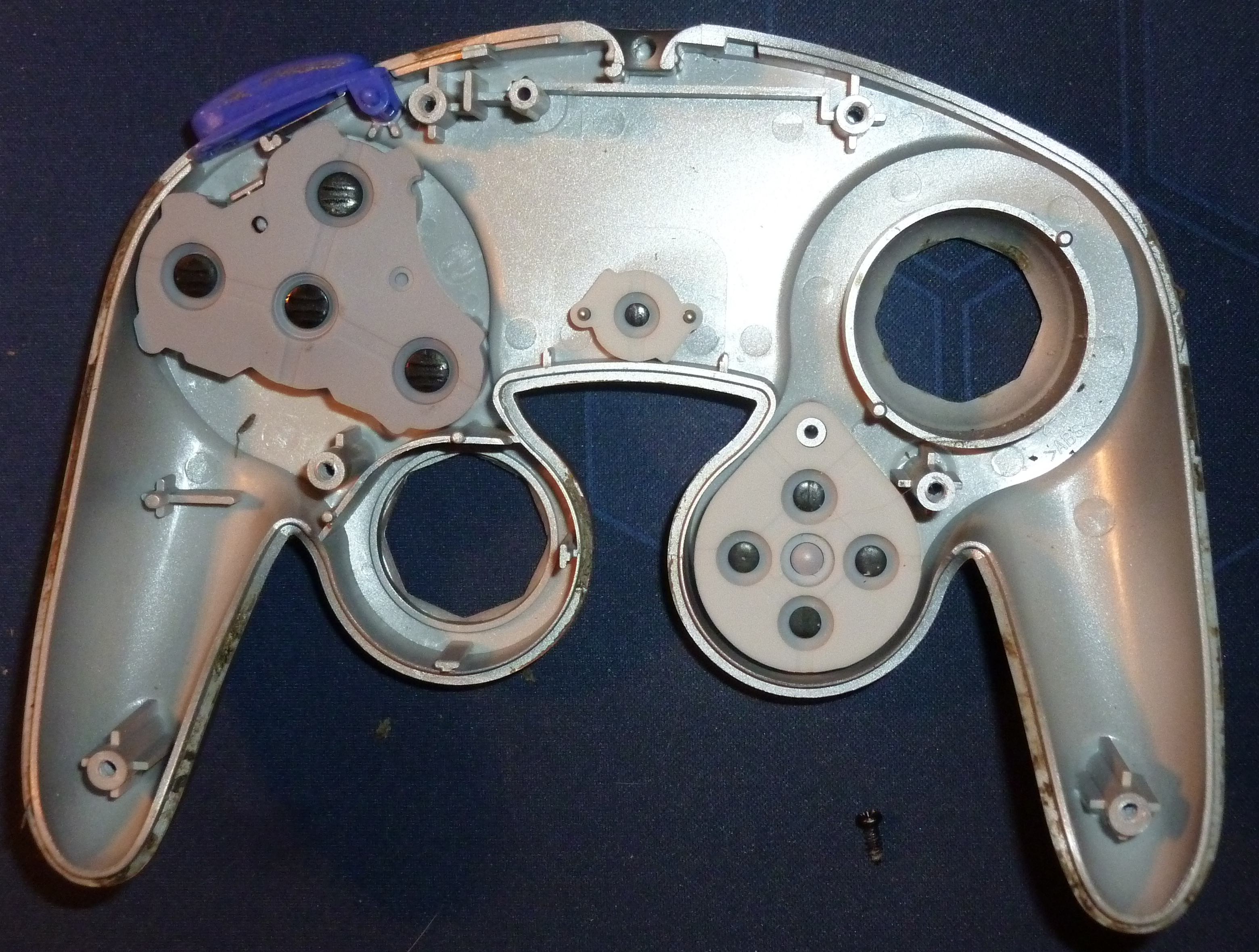
Here you have the two Top shells together....
...and the Bottoms:
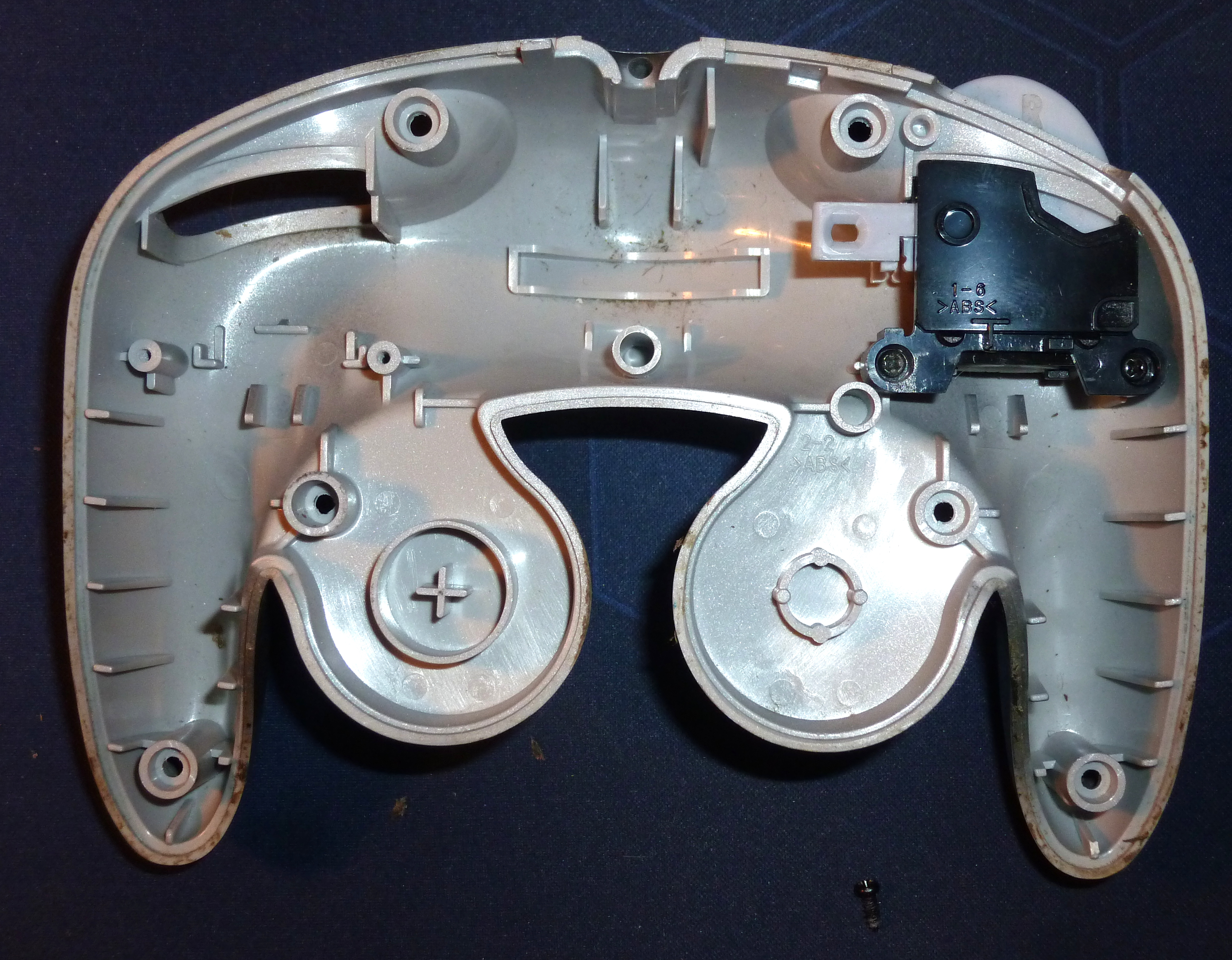
The left trigger is removed, you'll see later why.
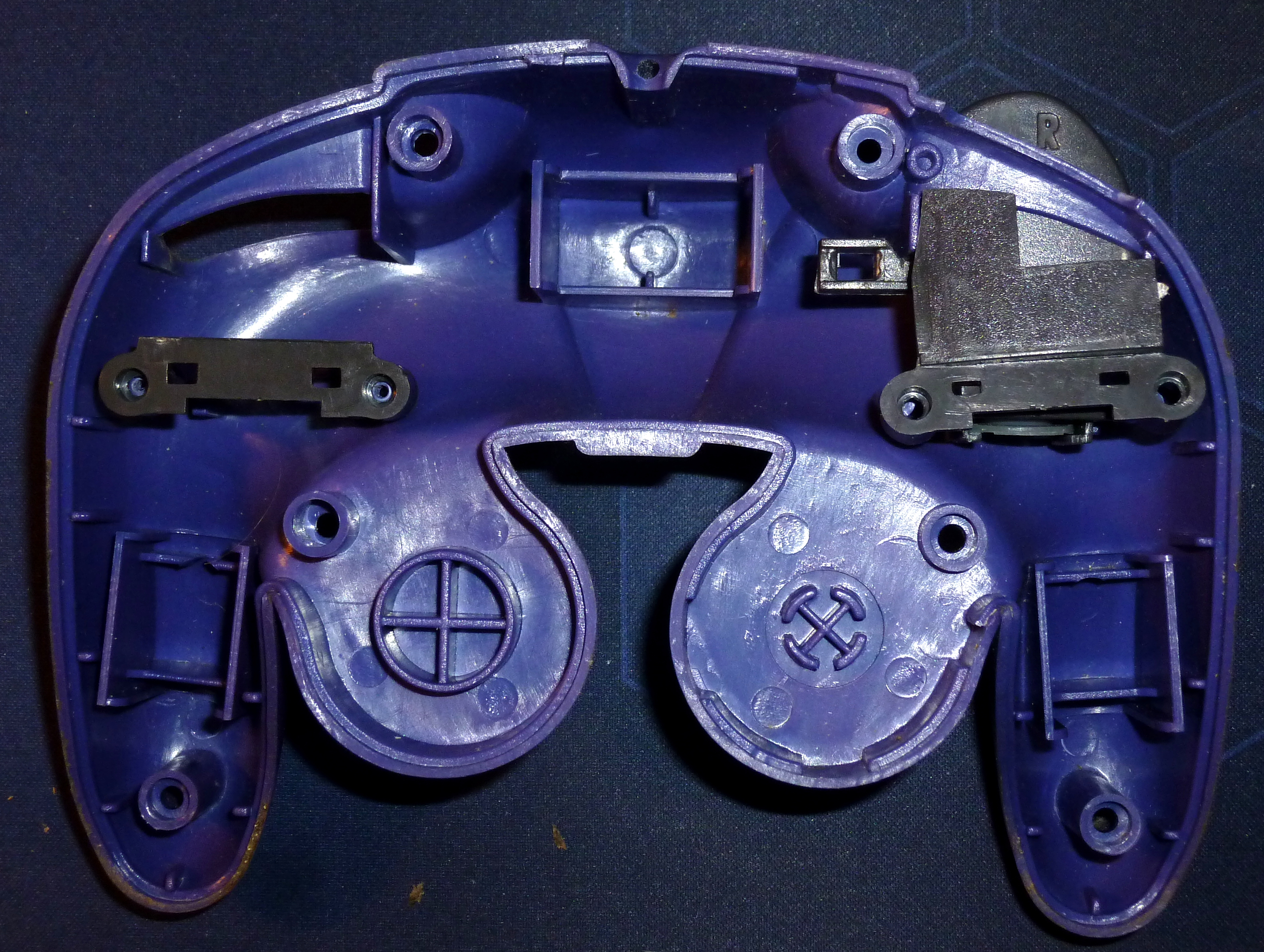
Basically the two are one and the same except a few details. The 3rGCC (the purple one, btw) is a bit wider.
Electronics:
IMO the second most interesting thing. I'll split that up a little wider, since the rest is almost only electronics
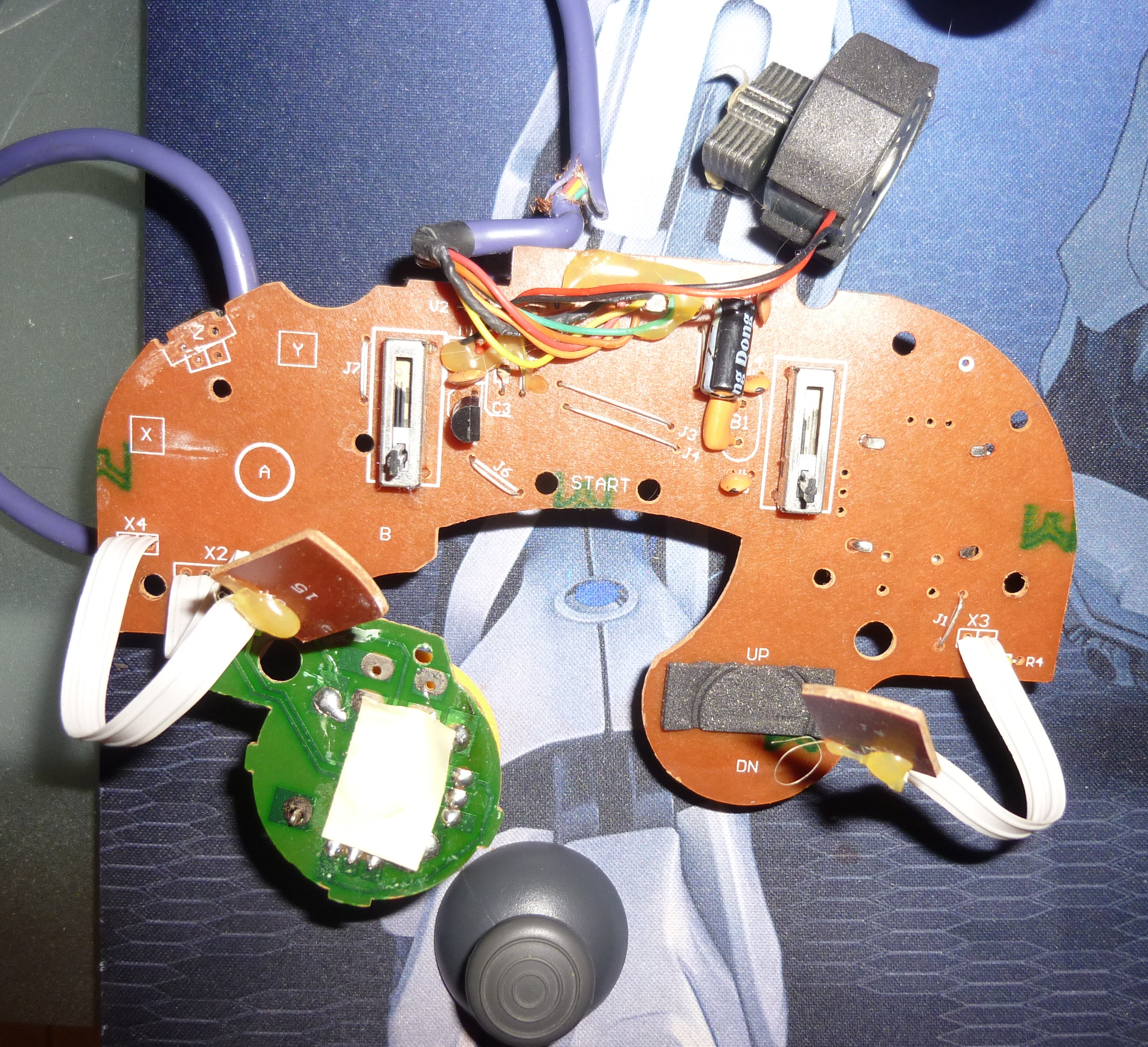
So first off, here you have the "Motherboard" of the 1pGCC.
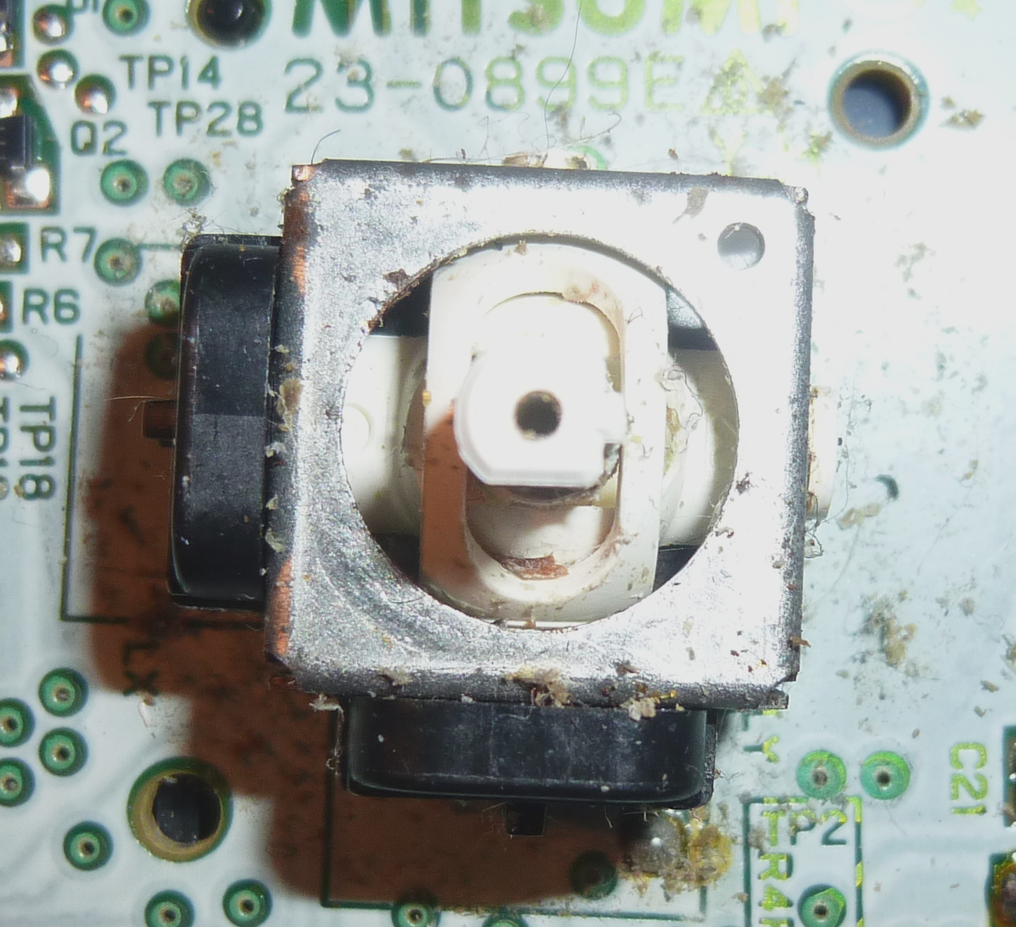
Looks like what one would except. So I decided to remove the control stick, with is also connected by plugging, and found something... special.
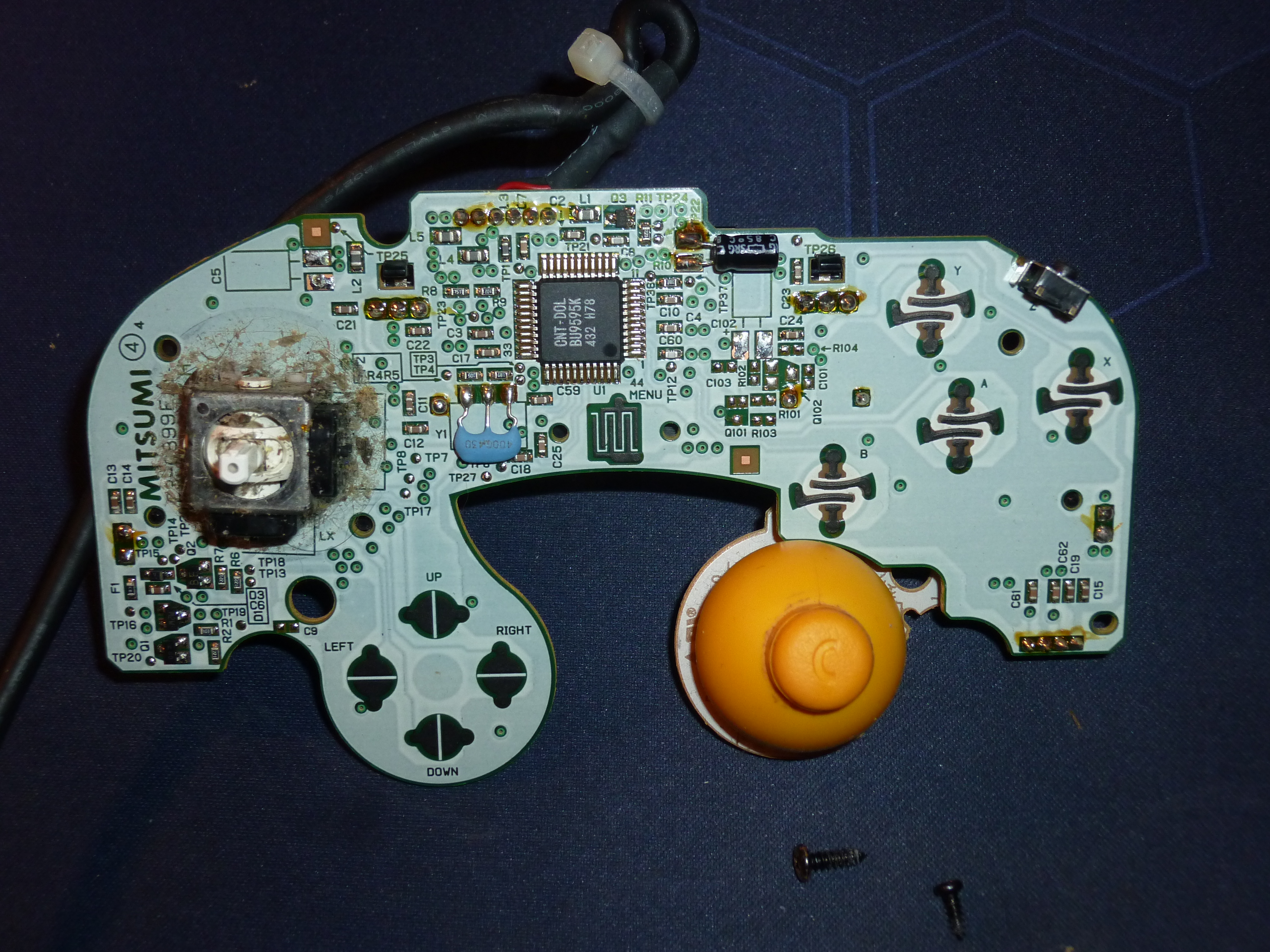
If your control stick isn't working properly anymore, you could now know why
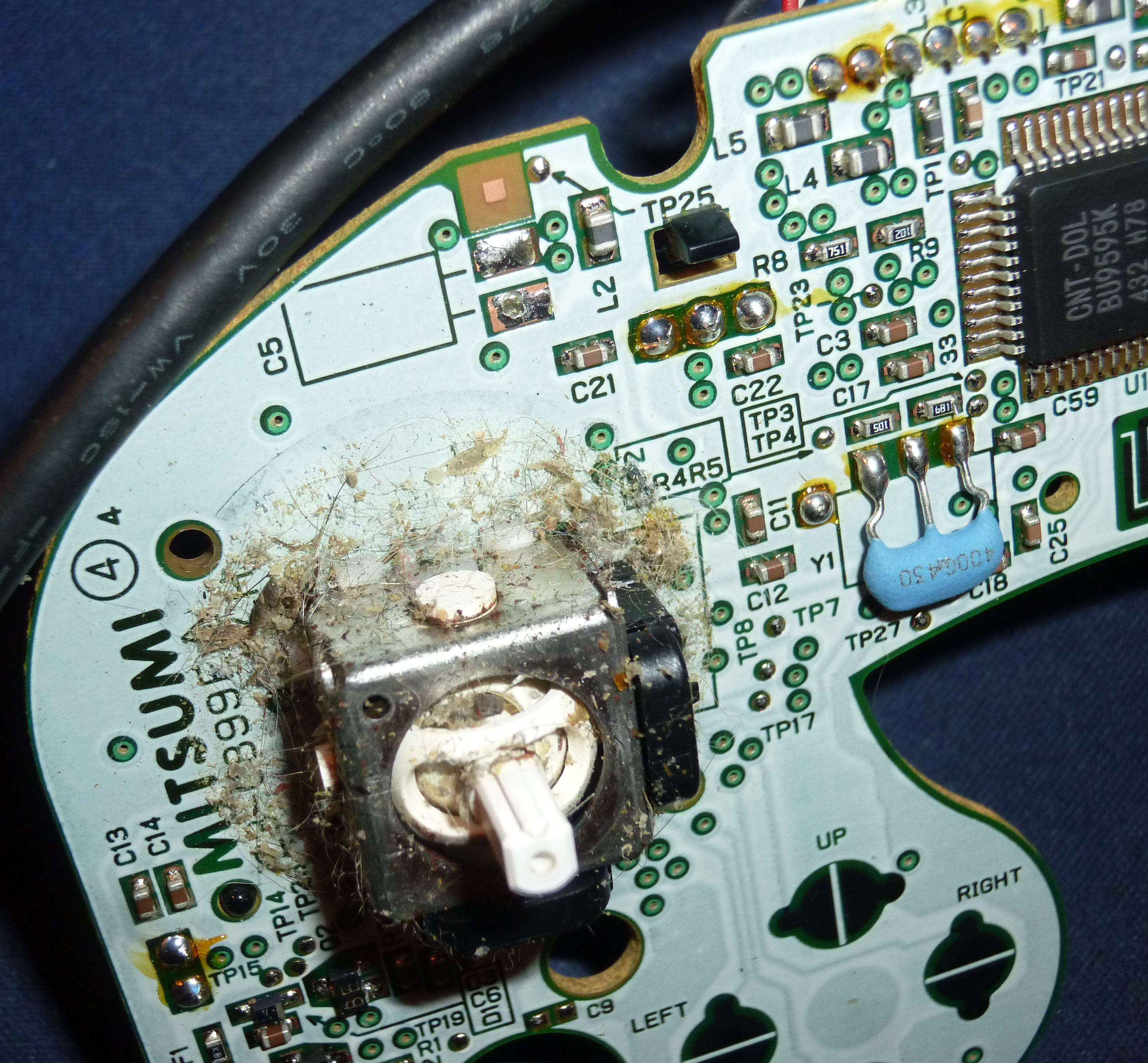
 No seriously, I laughed so hard when I saw that.
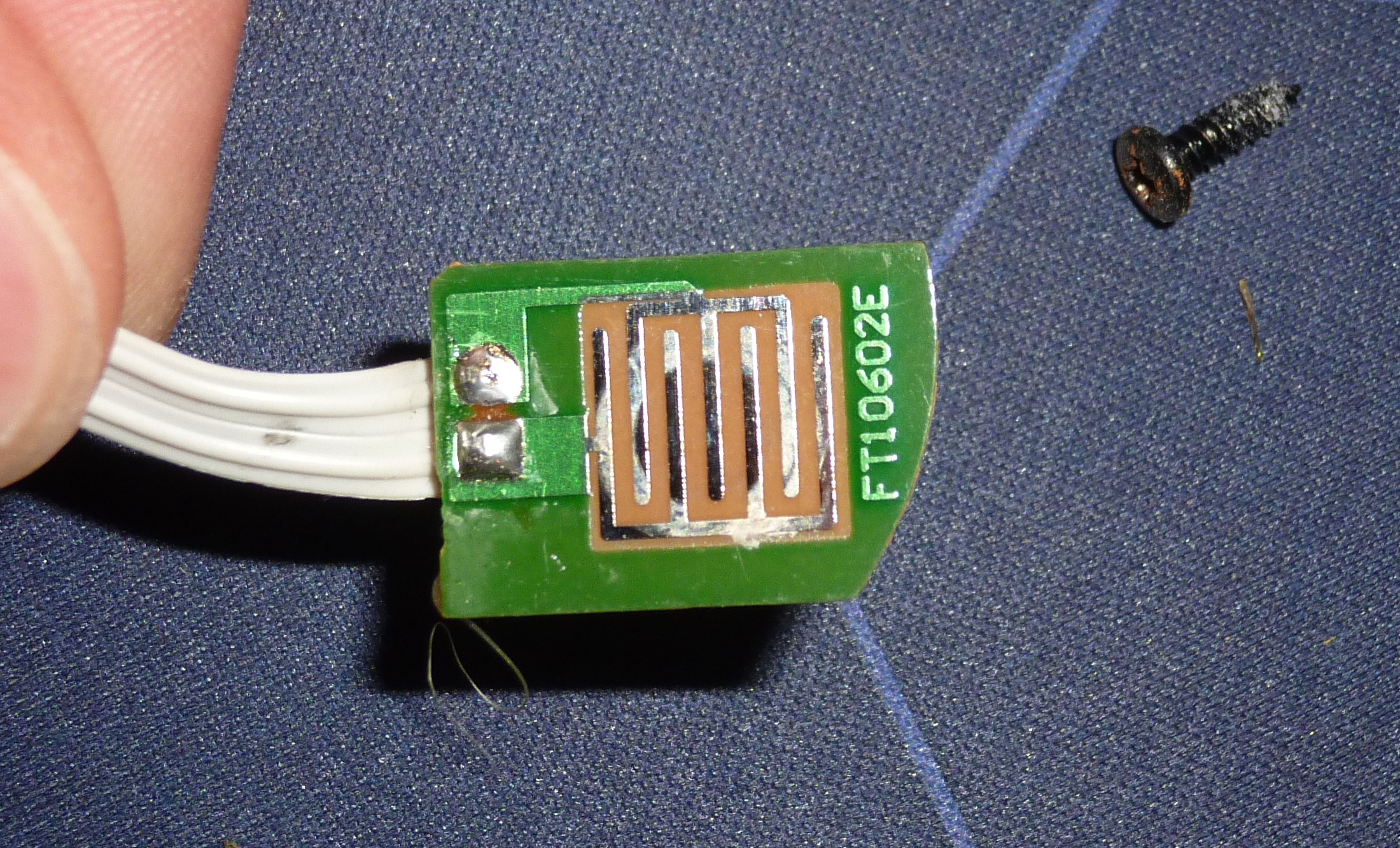
However, back to the picture before, a bit of explanation: Those little metal parts you can see are what reads and processes your inputs.
If you look back to the picture of the Top Shell you'll notice some round metal plates on the back of where the buttons are. Now when one of those buttons is pressed, it connects the four metal parts of the main board of the appending button, connect them and allow the electricity to flow. That's how computers basically work.
However, i honestly don't know why there are 4 and not two, but whatever.
The next rather interesting thing is on the back of the main board,
the Rumble.
The winner here is, once again, the 1pGCC. Why? The rumble is connected directly to the main board, and thus easy to handle.
I don't know how this one works, but it does. The 3pGGC's rumble on the other hand is kind of cool.
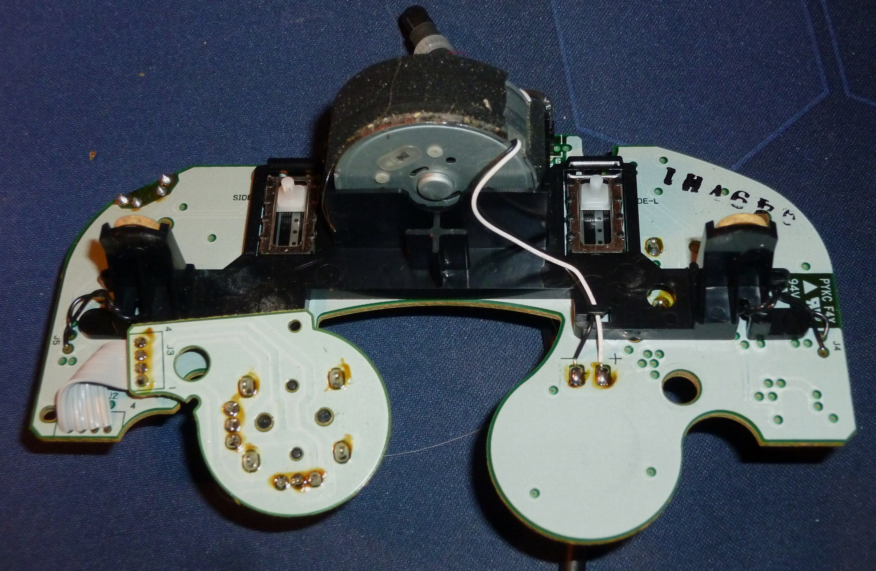
Take a look:
Can you figure how it works? Actually it's pretty simple but clever:
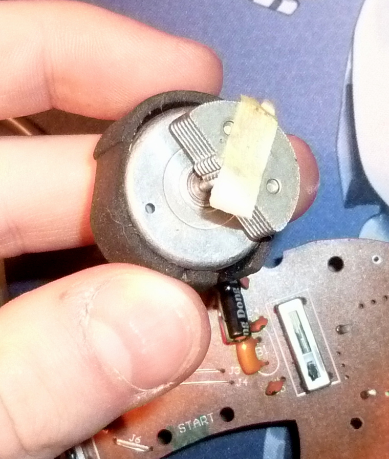
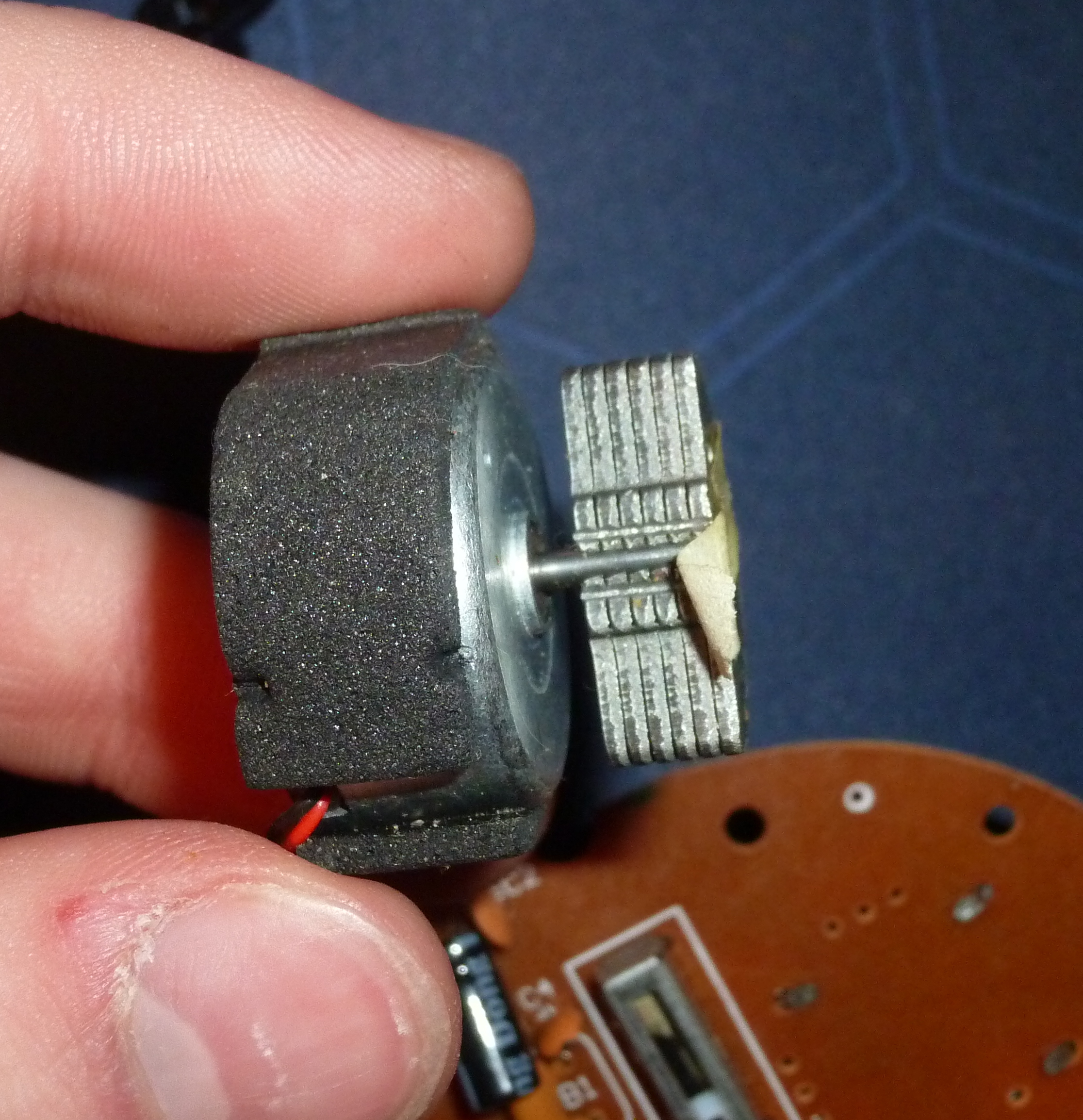
The electric motor brings the half-round metal part to rotation, and the controller starts shaking. And that half round metal part consists of many small plates, simply because the manufacturing is cheaper
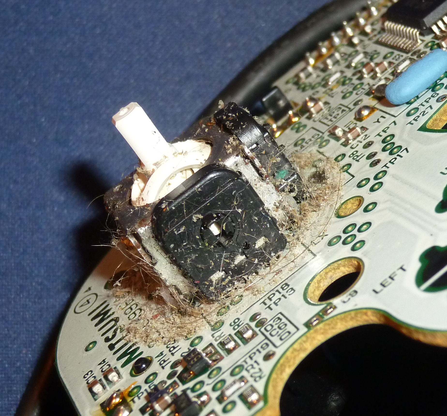
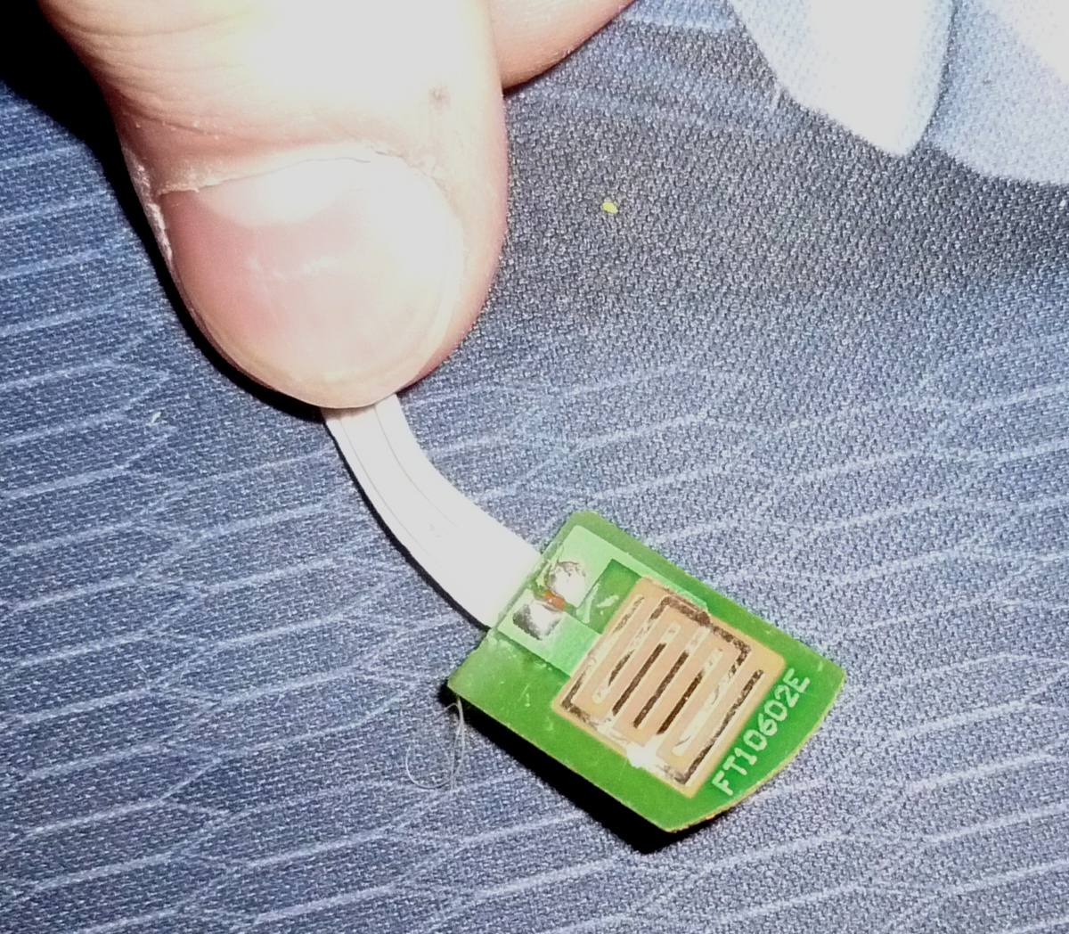
Control stick:
I was really surprised on how it worked. The control stick has like 2 spheres interleaved where one does the X and the other the Y axis... ok, it's hard to explain, maybe those pictures will help:
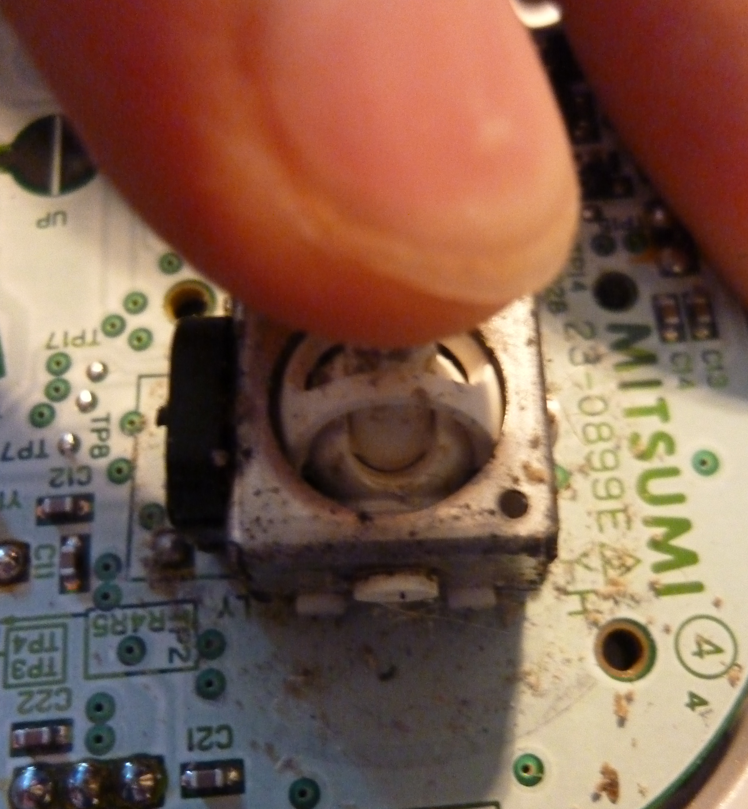
So that thing is quite cool, but it apparently stats loosening up a bit after usage (that's what happened to me as well. It was so loose it would go to random directions if idle)
And here 3p, quite similar, works as well.
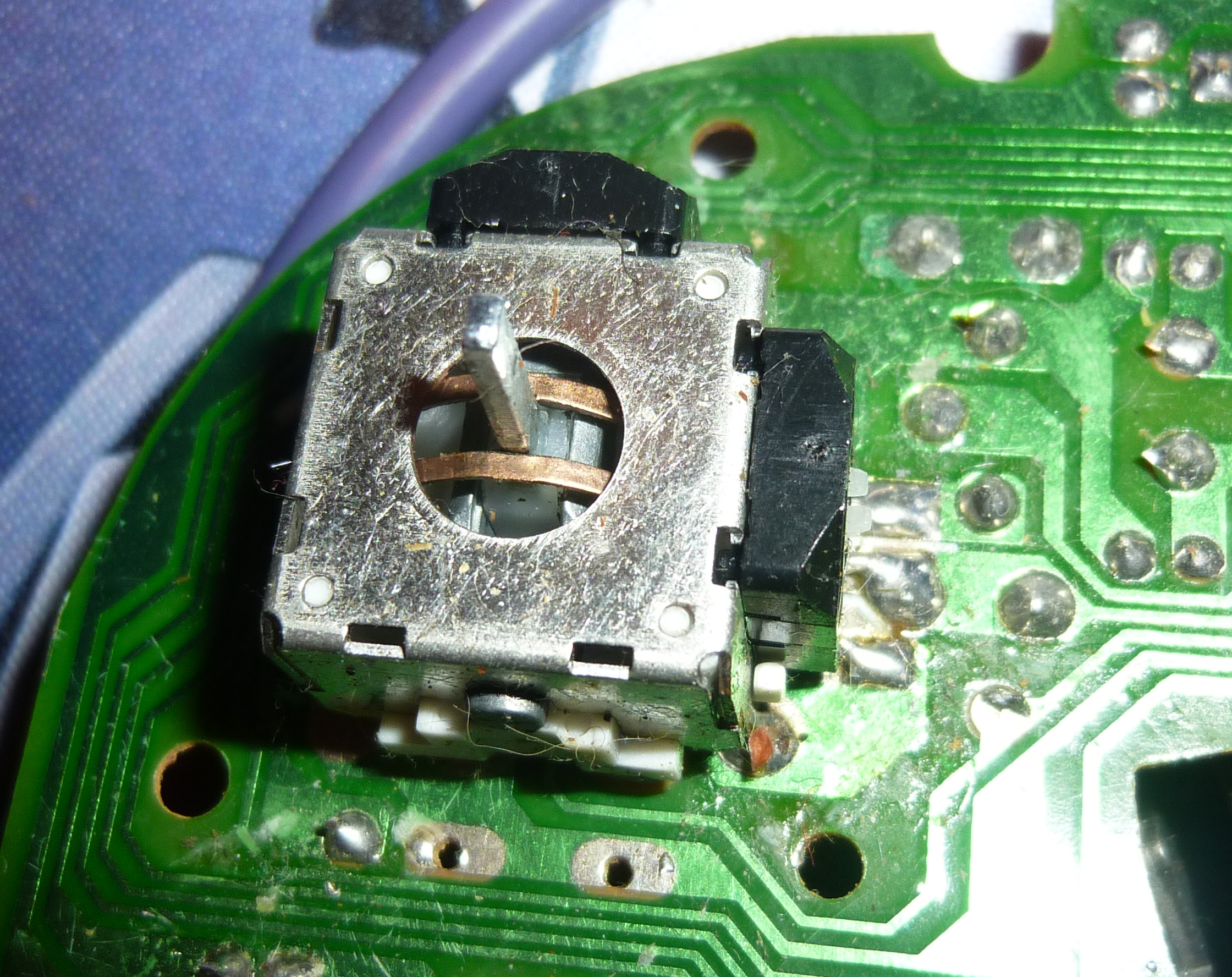
It seems like there's a spring inside, and the spring of the 3pGCC fells way stronger. However, I didn't use it too often, so that might be the reason...
Now, for all you Powershielder, Wavedasher and l-canceller out there, the most interesting part,
the triggers (are they even called trigger? Whatever)
L and R are both mounted in the bottom half of the shell. 1p and 3p use similar systems, but 3p needs an additional part that's mounted with screws to hold the trigger in place.
The triggers consist of 3 parts, but take a look yourself:
1p first. The two plastic parts go into each others, I just couldn't take a picture of that.

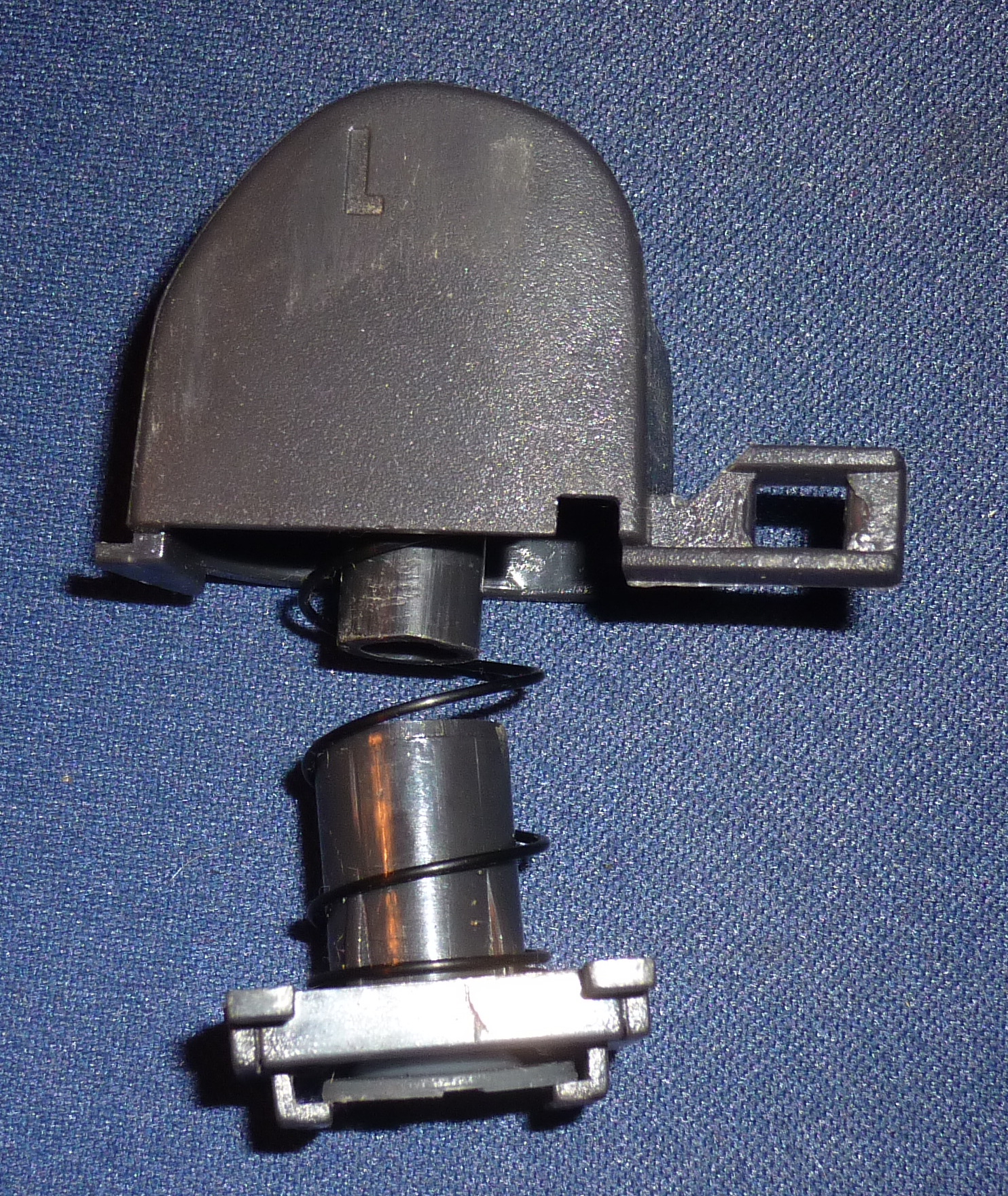
The triggers press on the following part,
where it once again connects the metal parts and allows electricity to flow. The connecters of 1st and 3rd p are completely identical.
Next up only the triggers:
Do you see that? Yes. Almost exactly the same thing
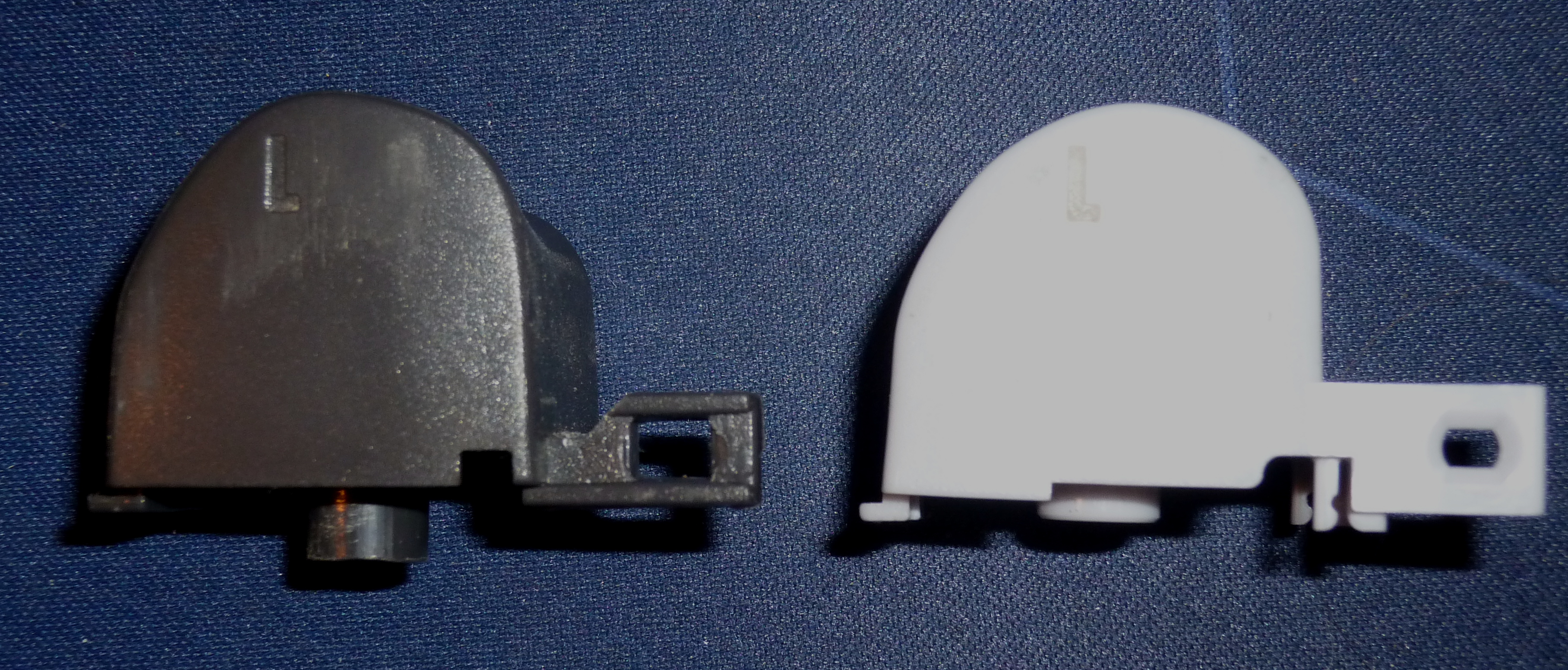 So you can switch triggers rather easily.
And even more interesting:
Physic tells us, the shorter the spring, the more force is used. Dark gray is 3p.
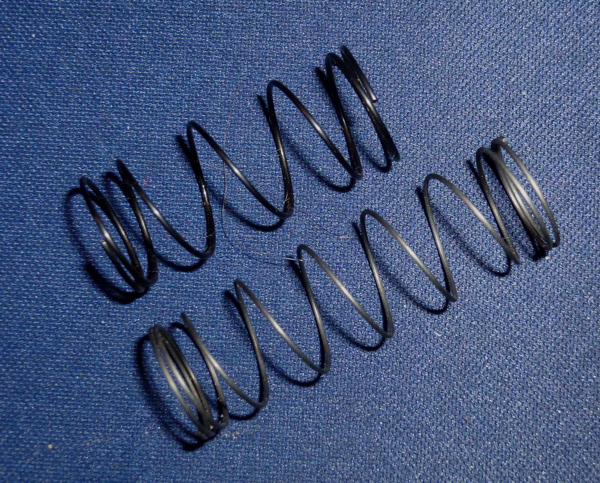
So it take more force to press L on the 3p.
So what did I do? since i couldn't really repair the Control stick, i went on and:
I replaced the L of the 1p with the one of the 3p, including its spring.
After a few tests I found pros and cons:
Complete con: 3p is a little bit longer, causing the trigger to stuck sometimes. Needs a bit of reworking, but works fine afterwards
Pro: Its ridiculously awesome to have R and L with completely different pressure forces. That's like, amazing. The 3p L gives u so much feedback, the moment you let it go it springs back in idle position. Where as the right one is really fast pressed. 3p is really good for Wavedashing, while as 1p works great for power shielding IMO.
However, my controller broke completely soon after, so I'm back to using normal GCC (I'm so glad i still found some. No really, getting those here in Switzerland is really hard. That was basically why I even started the hole thing)
Ok, with this I'm almost finished. If you have any questions feel free to ask.
Here a complete picture of my working ground and everything, and after it additional pictures. Thanks for reading
Legend:
1: Screwdrivers; 2: Bottom 3p; 3: Top 3p; 4: Control stick 3p; 5: Z 3p; 6: C-Stick 3p; 7: Rumble 3p; 8: R input 3p; 9: L cover 3p; 10: Top 1p; 11: Main board; 12: C-Stick; 13: Screws; 14: Springs; 15: L 1p; 16: Bottom 1p; 17: Control stick 1p; 18: Backside of the Buttons 1p, Z; Misc: 19: 20 sided Die... definitely not for D&D; 20: My mouse; 21: mouse board... for my mouse
; 22: my err... other mouse.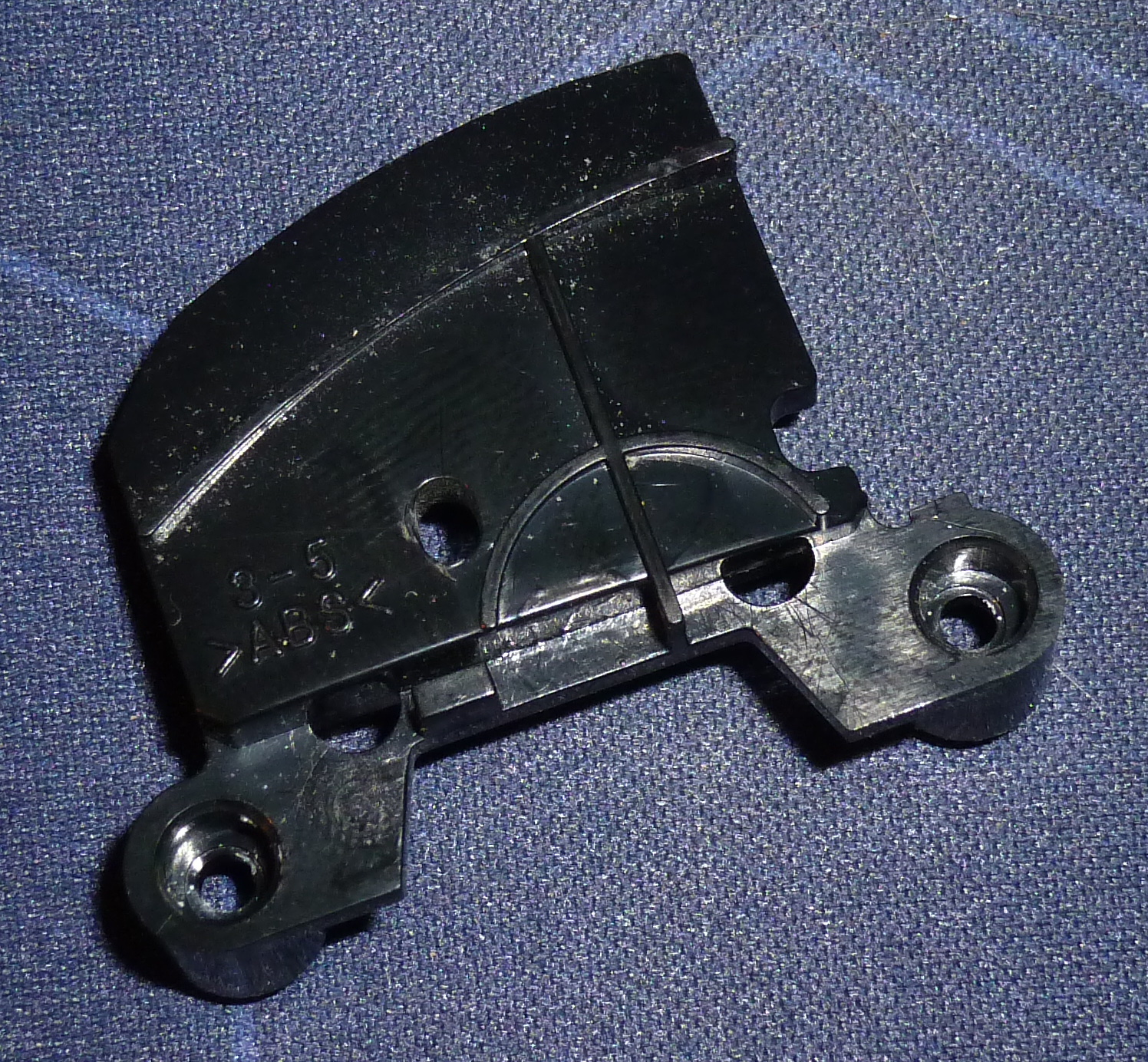
Have Fun!