v2.x
Smash Rookie
Hey guys,
I've been looking around and I never found a good place to find the pinouts for game cube controllers for things like LEDs. This will be an ongoing project since I'm not aware of differences in layout between models. I'll also be making a tutorial on how to do LEDs in the future, but I just wanted to post this for now for those who understand how to do so already and lack things such as a multimeter or the time to find proper points. I'm also hoping to consolidate guides when it comes to case modification, but we'll see how that goes.
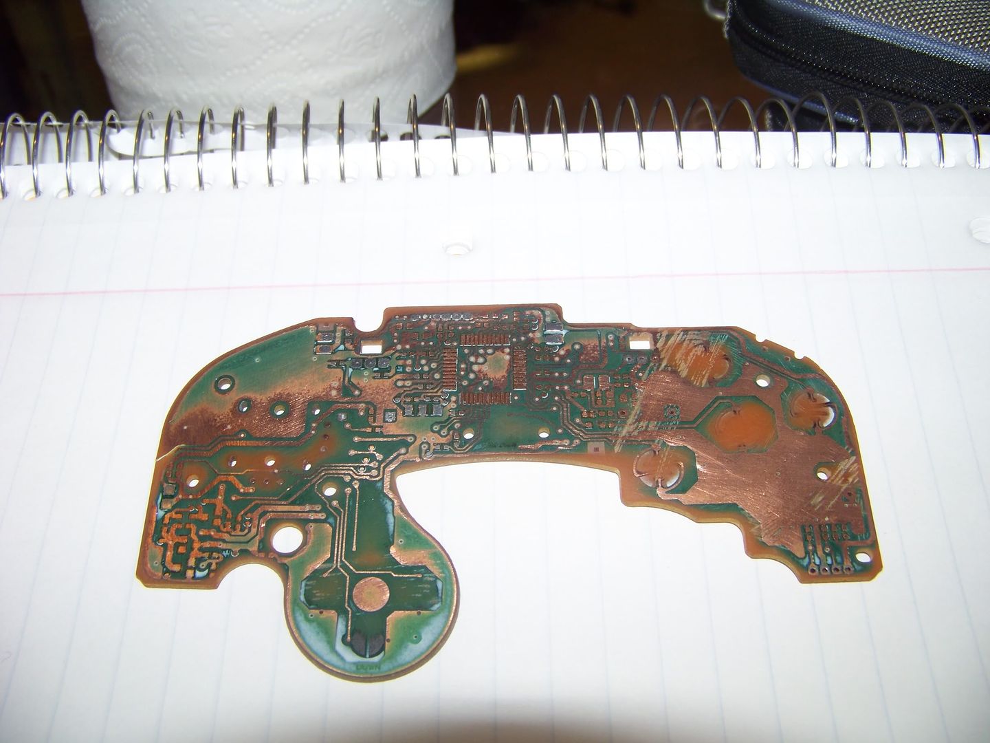
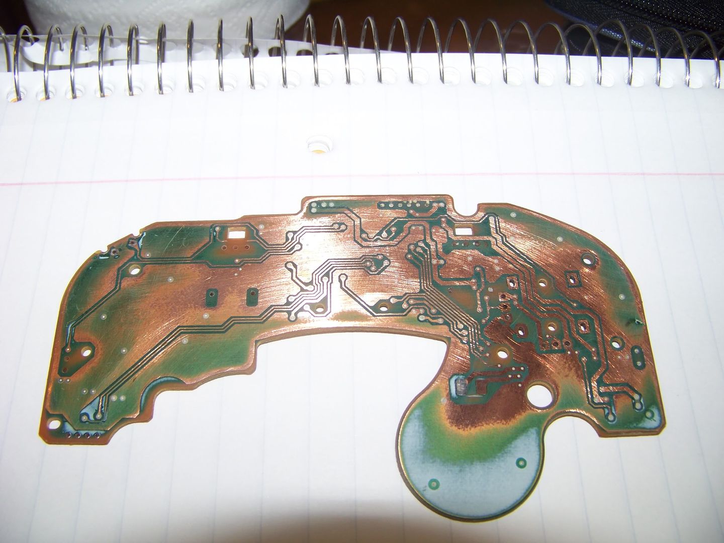
Here's an orange controller [labeled DOL-003 (Not sure if this is motherboard revision or not, if someone could further elaborate)]
If anyone has any feedback, I'd love to hear it.
More to come.
EDIT: Changed the title for clarification
I've been looking around and I never found a good place to find the pinouts for game cube controllers for things like LEDs. This will be an ongoing project since I'm not aware of differences in layout between models. I'll also be making a tutorial on how to do LEDs in the future, but I just wanted to post this for now for those who understand how to do so already and lack things such as a multimeter or the time to find proper points. I'm also hoping to consolidate guides when it comes to case modification, but we'll see how that goes.
Here's an orange controller [labeled DOL-003 (Not sure if this is motherboard revision or not, if someone could further elaborate)]
If anyone has any feedback, I'd love to hear it.
More to come.
EDIT: Changed the title for clarification
Last edited: